Abstract
Optical fibers serve as essential components in modern communication infrastructures, enabling the reliable transmission of large volumes of data across long distances with exceptionally low attenuation. The performance of these fibers is governed by several key factors, including the physical geometry of the fiber, the refractive-index distribution between the core and cladding, and the overall efficiency with which light is confined and guided within the core region. A comprehensive understanding of these parameters is crucial for predicting system behavior and optimizing fiber design for a wide range of applications. In this work, light propagation in both single-core and dual-core optical fibers is investigated using a simplified yet effective ray-tracing model. This modeling approach provides intuitive visualizations of ray trajectories and enables a quantitative analysis of the guided power fraction as a function of the launch angle. By examining how different launch conditions influence the proportion of light that remains confined within the fiber, the model offers insight into the mechanisms underlying mode propagation and coupling behavior in various fiber configurations. The results obtained from the simulations contribute both an instructive and predictive framework for evaluating the optical performance of single-core and dual-core fibers. This framework facilitates direct comparison between the two configurations and highlights their respective advantages, particularly in terms of light-guiding efficiency and potential application domains. Overall, the study demonstrates that simplified ray-based analyses can serve as valuable tools for understanding complex optical processes and guiding the development of improved fiber-based technologies.
Keywords
Optical Fiber, Ray-tracing, Guided Power Fraction, Single-core Fiber, Dual-core Fiber, Acceptance Angle,
Numerical Simulation
1. Introduction
The optical fibers constitute the backbone of modern communication systems, enabling high-speed data transmission over long distances with minimal losses. The performance of an optical fiber primarily depends on its geometry, the refractive index distribution, and its ability to guide light efficiently.
| [1] | Ghatak, A., & Thyagarajan,K. Introduction to Fiber Optics. Cambridge University Press, 1998. |
[1]
Among the most common configurations, single-core fibers are widely employed in telecommunications applications, while dual-core fibers offer additional capabilities in coupling, multiplexing, and multimode guidance.
| [2] | Keiser, G. Optical Fiber Communications (5th ed.). McGraw?Hill Education, 2021. |
[2]
.
The fraction of guided power in a fiber is a key indicator of its efficiency. It represents the proportion of optical energy that remains confined within the core and can therefore be transmitted to the output with minimal losses. The determination of this fraction depends on the input conditions particularly the incidence angle of the light rays as well as on the physical properties of the fiber, such as the refractive indices of the core and cladding and the core radius.
| [3] | Snyder, A. W., & Love, J. D. Optical Waveguide Theory. Chapman and Hall, 1983. |
[3]
.
The objective of this study is to compare light guidance in single-core and dual-core fibers using a simplified ray-tracing model. This approach enables visualization of the ray trajectories and quantification of the guided power fraction as a function of the launch angle, thereby providing an instructive and predictive tool for analyzing optical performance.
2. Mathematical Modeling of the Single-core Fiber
The Light propagation in a multimode optical fiber can be approximated using the ray model, in which the optical field is represented as a set of straight rays propagating through the fiber core. Each ray is characterized by its launch angle
with respect to the fiber axis and its initial radial position
.
| [4] | Marcuse, D. Theory of Dielectric Optical Waveguides. Academic Press, 1991. |
[4]
.
For a single-core fiber, the main physical parameters are:
1). : refractive index of the core
2). : refractive index of the cladding
3). : core radius
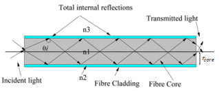
Figure 1 illustrates the main physical parameters of a single-core optical fiber, showing the core refractive index (
), the cladding refractive index (
), and the core radius (
).
Figure 1. Illustration of , , .
In a single-core optical fiber, represents the refractive index of the core, which determines how strongly light is guided within the fiber. is the refractive index of the cladding, slightly lower than that of the core, which ensures total internal reflection and keeps the light confined. The denotes the radius of the core, defining the physical region through which the light propagates.
The numerical aperture (NA) of the fiber, which determines the maximum acceptance angle , is defined as:
An incident ray at the fiber input is considered guided if its final radial position , after propagation over a distance , remains within the core region:
In this simplified model, rays are assumed to propagate in straight lines; that is, no internal reflection is taken into account. The final radial position is therefore approximated by:
3. Materials and Methods
Designing a dual-core fiber requires selecting materials with a controlled difference in refractive index between the core and cladding regions. To achieve this, we will implement the presence of two cores in the mathematical modeling of the fiber and then simulate the results in MATLAB.
| [5] | Kawanishi, S., & Saruwatari, M. “Coupling Characteristics of Dual?Core Optical Fibers.” IEEE Journal of Quantum Electronics, 18(10), 1533-1541, 1982.
https://doi.org/10.1109/JQE.1982.1071448 |
| [6] | Fu, H. Y., Tam, H. Y., Shao, L. Y., Lu, C., & Dong, X. “Dual?Core Photonic Crystal Fiber Sensors.” IEEE Sensors Journal, 12(5), 1208-1213, 2012.
https://doi.org/10.1109/JSEN.2012.2190185 |
| [7] | Peng, G.-D. (Ed.). Handbook of Optical Fibers. Springer, 2018. https://doi.org/10.1007/978-981-10-6310-6 |
[5-7]
.
3.1. Modeling the Dual-core Fiber
For a ray launched at an initial radial position and angle relative to the fiber axis:
The dual-core fiber consists of:
1). an inner core of radius and refractive index ;
2). an outer core of radius and refractive index ;
3). an external cladding of radius and refractive index .
A ray is considered guided if it remains within the outer core radius:
The numerical aperture (NA) is calculated based on the highest refractive index relative to the cladding:
This simplification allows a direct analytical comparison of the guiding performance between the two fiber types while maintaining a straightforward computational approach.
3.2. Methodology Simulation Parameters
The parameters used in the numerical simulation are summarized below:
Table 1. Fiber modeling parameters used in MATLAB.
Parameter | Single-core fiber | Dual-core fiber |
Core refractive index | 1.48 | 1.48 (inner), 1.46 (outer) |
Cladding refractive index | 1.45 | 1.45 |
Core radius | 4 µm | 4 µm (inner), 8 µm (outer), 62.5 µm (cladding) |
Simulated length | 100 µm | 100 µm |
Number of rays | 500 | 500 |
The simulation parameters listed in
Table 1 were selected to represent typical optical fiber characteristics. The single-core fiber uses a core refractive index of 1.48 and a radius of 4 µm, while the dual-core fiber includes an inner core of 4 µm (
) and an outer core of 8 µm (
), with a cladding of 62.5 µm (
). The simulated propagation length of 100 µm and 500 rays provide sufficient resolution for analyzing ray trajectories and guided power fractions.
Varying these parameters could significantly affect the results:
1). Core refractive index: Increasing the index contrast between the core(s) and cladding enlarges the numerical aperture, enabling higher launch angles to be guided.
2). Core radius: Larger cores increase the spatial guiding region, enhancing tolerance to misaligned or off-axis rays.
3). Number of rays: A higher number of simulated rays improves statistical accuracy of the guided power fraction, while fewer rays could lead to variability.
4). Propagation length: Extending the simulated length could reveal additional effects such as longitudinal dispersion and mode interference, which are not captured in the current 100 µm simulations.
Including such parametric variations in future work would provide deeper insight into fiber performance optimization and the practical applicability of single-core versus dual-core configurations.
3.3. Calculation of the Guided Power Fraction
For each ray:
1). Compute the final radial position e based on the launch angle .
2). Assign a binary value:
(9)
3). Compute the cumulative guided power fraction:
This procedure allows the generation of guided power fraction versus launch angle curves for both fibers.
| [8] | Savović, S., Dai, W., Djordjevich, A., Aidinis, K., Li, Z., & Min, R. “Influence of launch beam distribution on power flow and angular division multiplexing in seven-core silica optical fibers.” Frontiers in Physics, 10, Article 993738, 2022.
https://doi.org/10.3389/fphy.2022.993738 |
[8]
.
3.4. Visualization
1). Typical ray trajectories: Three representative launch angles are plotted for each fiber to illustrate the paths of rays within the cores.
2). Fiber cores: The radial boundaries of the cores are shown to highlight the guiding regions.
3). Guided power curves: The cumulative guided power fraction is plotted as a function of the launch angle, providing a visual representation of the acceptance characteristics of each fiber.
| [9] | Hu, D. J. J., Liu, L., Dong, H., & Zhang, H. “Design of a Broadband Fiber Optic Mode Coupler for Multimode Optical Coherence Tomography (OCT) in the O?band.” Photonics, 10(2), 162, 2023. https://doi.org/10.3390/photonics10020162 |
[9]
.
4. Results
Light propagation in optical fibers depends on the core geometry, refractive indices, and launch conditions. Single-core fibers provide simple guiding, while dual-core fibers can expand the guiding region and enable core-to-core interactions. Using a simplified ray-tracing model, we analyzed ray trajectories and the guided power fraction as a function of launch angle. The following section presents the simulation results for both fiber types.
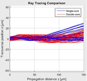
Figure 2. Ray Tracing Comparison.
Figure 1 shows the propagation of multiple rays in single-core (blue) and dual-core (red) fibers over a distance of 150 µm.
1. Single-core fiber (blue):
The rays remain confined within the fiber core and reflect off the core boundaries (). All rays remain centered around the fiber axis, illustrating the principle of total internal reflection, typical of single-mode or simple multimode fibers. The confinement is tight, which limits the spatial dispersion of the rays.
2. Dual-core fiber (red):
The rays propagate within the inner core and can reach the outer core. Reflections are simulated at the outer core boundaries (). The rays occupy a larger transverse area than in the single-core fiber, showing that the presence of the second core expands the propagation region and could allow coupling between cores.
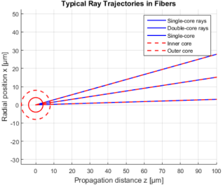
Figure 3. Typical Ray Trajectories in Fibers.
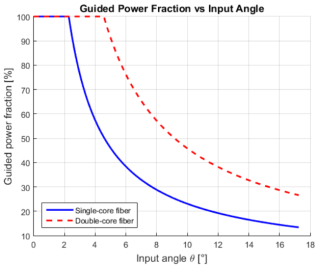
Figure 4. Guided Power Fraction vs Input Angle.
4.1. Acceptance Angles
The acceptance angle of an optical fiber defines the maximum launch angle at which light can be efficiently guided within the core. It is a key parameter that determines the fiber’s ability to capture and confine light. The following section presents the calculated acceptance angles for both single-core and dual-core fibers.
The calculations yield:
1). Single-core fiber:
2). Dual-core fiber:
This similarity is explained by the fact that the region with the highest refractive index in the dual-core fiber determines the overall numerical aperture.
4.2. Ray Trajectories
Analyzing the paths of individual rays provides a clear visualization of light confinement within the fiber cores. This section examines typical ray trajectories for both single-core and dual-core fibers under different launch angles.
1). Low-angle rays () propagate near the fiber axis and are fully guided.
2). Intermediate-angle rays () approach the core boundaries.
3). Rays close to interact with the core edges and may be lost if their final radial position exceeds the critical radius.
The
Figure 2 illustrates these behaviors, with single-core fiber rays in blue and dual-core fiber rays in red dashed lines. The cores are overlaid to visualize the guiding region.
4.3. Guided Power Fraction
The
Figure 3 shows the guided power fraction as a function of the launch angle:
1). For , 100% of rays are guided in both fibers.
2). As increases, the guided fraction gradually decreases.
3). For , no rays remain guided.
This behavior reflects the influence of the launch angle on the fiber’s ability to confine light.
5. Discussion
The simulation results provide insights into the guiding behavior of single-core and dual-core fibers, summarizing the main observations regarding ray trajectories and the fraction of guided power.
5.1. Fiber Comparison
The dual-core fiber provides a wider guiding region due to the addition of the second core (larger outer radius), which can improve tolerance to higher launch angles. However, in our simplified model, the maximum guided power fraction is similar to that of the single-core fiber because all rays originate from the center and do not undergo multiple reflections
| [10] | Jørgensen, A. A., Kong, D., Henriksen, M. R., Klejs, F., Ye, Z., Helgason, Ò. B., Hansen, H. E., Hu, H., Yankov, M., Forchhammer, S., Andrekson, P., Larsson, A., Karlsson, M., Schröder, J., Sasaki, Y., Aikawa, K., Thomsen, J. W., Morioka, T., Galili, M., Torres?Company, V., & Oxenløwe, L. K. “Petabit?per?second data transmission using a chip?scale microcomb ring resonator source.” Nature Photonics, 16, 798-802 (2022). https://www.nature.com/articles/s41566-022-01082-z |
[10]
.
The expanded guiding region indicates that dual-core fibers could enhance performance in systems requiring multimode guidance or mode multiplexing, such as high-capacity telecommunication networks or multimode sensor applications
| [11] | Zhou, W., Zhang, Z., Chen, H., Tsang, H. K., & Tong, Y. “Ultra?Compact and Efficient Integrated Multichannel Mode Multiplexer in Silicon for Few?Mode Fibers.” Laser & Photonics Reviews, 18(4), Article 2300460, 2024.
https://doi.org/10.1002/lpor.202300460researchportal.hkust.edu.hk |
| [12] | Cheng, L., Mao, S., Chen, Z., Wang, Y., Zhao, C., & Fu, H. Y. “Ultra-compact dual?mode mode-size converter for silicon photonic few?mode fiber interfaces.” Optics Express, 29(21), 33728-33740, 2021. https://doi.org/10.1364/OE.438839 |
[11, 12]
. The broader spatial confinement may allow more flexible coupling of modes and increased tolerance to misalignment during light injection.
5.2. Model Limitations
While the simplified ray-tracing approach provides useful pedagogical insights, several limitations must be considered for quantitative interpretation:
1). Absence of internal reflections: In real multimode fibers, rays undergo multiple reflections at the core–cladding interface. Neglecting these reflections likely underestimates guided power, particularly at higher launch angles
| [11] | Zhou, W., Zhang, Z., Chen, H., Tsang, H. K., & Tong, Y. “Ultra?Compact and Efficient Integrated Multichannel Mode Multiplexer in Silicon for Few?Mode Fibers.” Laser & Photonics Reviews, 18(4), Article 2300460, 2024.
https://doi.org/10.1002/lpor.202300460researchportal.hkust.edu.hk |
[11]
.
2). Neglect of radial distribution: All rays are launched from the fiber axis, whereas in practical setups, light can enter at different radial positions. This simplification limits the model’s accuracy in predicting mode excitation and spatial power distribution
| [12] | Cheng, L., Mao, S., Chen, Z., Wang, Y., Zhao, C., & Fu, H. Y. “Ultra-compact dual?mode mode-size converter for silicon photonic few?mode fiber interfaces.” Optics Express, 29(21), 33728-33740, 2021. https://doi.org/10.1364/OE.438839 |
[12]
.
3). Core-to-core interactions in dual-core fibers: The model does not consider coupling or hybrid modes between the inner and outer cores. In reality, these interactions can significantly modify power distribution and effective propagation, especially in applications involving mode multiplexing or integrated photonics
| [13] | Pita Ruiz, J. L., Dalvand, N., & Ménard, M. “Ultra-Compact Silicon Nitride Devices for High?Density Integration.” arXiv, 2025. arXiv: 2505.02662. not yet assigned (preprint) arXiv. |
| [14] | Tong, Y., Wu, W., & Tsang, H. K. “Efficient Mode Multiplexer for Few?Mode Fibres Using Integrated Silicon-on-Insulator Grating Coupler.” Student Paper, ECIO Conference, 2019. |
[13, 14]
.
4). Short propagation length: Simulations are limited to 100 µm, whereas real optical fibers extend over kilometers. Longitudinal effects such as dispersion, mode interference, and attenuation are therefore neglected.
To address these limitations, future work could employ more realistic simulation techniques, such as the beam propagation method (BPM) or finite-difference time-domain (FDTD) approaches, along with experimental validation of guided power fractions and mode profiles
. Comparing simulation results with experimental data would improve confidence in the predicted fiber performance.
5.3. Physical Interpretation and Practical Implications
Despite the simplifications, the study provides:
1). Quantification of tolerated launch angles for single-core and dual-core fibers.
2). Visual comparison of ray confinement and trajectories.
3). Pedagogical insight into how core radius and refractive index affect guiding efficiency.
The differences between single-core and dual-core fibers have practical implications. Dual-core fibers may offer enhanced tolerance to high launch angles, which is beneficial for high-capacity optical transmission systems and mode-division multiplexing
| [10] | Jørgensen, A. A., Kong, D., Henriksen, M. R., Klejs, F., Ye, Z., Helgason, Ò. B., Hansen, H. E., Hu, H., Yankov, M., Forchhammer, S., Andrekson, P., Larsson, A., Karlsson, M., Schröder, J., Sasaki, Y., Aikawa, K., Thomsen, J. W., Morioka, T., Galili, M., Torres?Company, V., & Oxenløwe, L. K. “Petabit?per?second data transmission using a chip?scale microcomb ring resonator source.” Nature Photonics, 16, 798-802 (2022). https://www.nature.com/articles/s41566-022-01082-z |
| [15] | (Additional) Geng, Y., et al. “Coherent optical communications using coherence-cloned Kerr soliton microcombs.” Nature Communications, 13, 1070, 2022.
https://doi.org/10.1038/s41467-022-28052-8 |
[10, 15]
. They are also suitable for integrated photonic devices where mode coupling is critical, such as mode multiplexers, multi-channel sensors, or compact telecommunication modules
| [11] | Zhou, W., Zhang, Z., Chen, H., Tsang, H. K., & Tong, Y. “Ultra?Compact and Efficient Integrated Multichannel Mode Multiplexer in Silicon for Few?Mode Fibers.” Laser & Photonics Reviews, 18(4), Article 2300460, 2024.
https://doi.org/10.1002/lpor.202300460researchportal.hkust.edu.hk |
| [12] | Cheng, L., Mao, S., Chen, Z., Wang, Y., Zhao, C., & Fu, H. Y. “Ultra-compact dual?mode mode-size converter for silicon photonic few?mode fiber interfaces.” Optics Express, 29(21), 33728-33740, 2021. https://doi.org/10.1364/OE.438839 |
| [13] | Pita Ruiz, J. L., Dalvand, N., & Ménard, M. “Ultra-Compact Silicon Nitride Devices for High?Density Integration.” arXiv, 2025. arXiv: 2505.02662. not yet assigned (preprint) arXiv. |
| [14] | Tong, Y., Wu, W., & Tsang, H. K. “Efficient Mode Multiplexer for Few?Mode Fibres Using Integrated Silicon-on-Insulator Grating Coupler.” Student Paper, ECIO Conference, 2019. |
[11-14]
.
Figure 4 can be interpreted as the fiber’s angular transfer function: low-angle rays are fully transmitted, while rays approaching the maximum acceptance angle experience partial loss. This illustrates the fiber’s limitations and provides a framework for designing fibers with desired acceptance characteristics. Additionally, the results suggest that careful design of core dimensions and refractive indices can optimize performance for specific applications, including telecommunication networks and multimode sensing systems.
6. Conclusion
This study presented a simplified ray-tracing approach to analyze the guided power fraction in single-core and dual-core optical fibers. The results show that both fiber types have a comparable acceptance angle ( ≈ 17°) and that the guided power fraction strongly depends on the launch angle, with optimal confinement observed at low angles.
The dual-core fiber demonstrates the potential to expand the guiding region, although this effect remains limited within the framework of the simplified model used.
Future work includes the introduction of internal reflections to simulate realistic propagation modes, consideration of a radial distribution of input rays to better reproduce experimental conditions, and the study of core-to-core coupling to refine the characterization of multi-core fibers.
This approach thus provides a simple yet effective tool for quantifying and comparing the guiding performance of optical fibers and offers a solid basis for more realistic simulations of complex multimode fibers.
Abbreviations
| Guided Power Fraction |
| Number of Simulated Rays |
| Numerical Aperture |
| Launch/Entry Angle of the Ray |
| Maximum Acceptance Angle |
| Radius of the Single-core Fiber |
| Radius of the Inner Core |
| Radius of the Outer Core |
| Radius of the Cladding |
| Initial Radial Position of the Ray |
| Radial Position of the Ray at Axial Distance z |
Author Contributions
Randriana Heritiana Nambinina Erica: Conceptualization, Methodology, Writing – original draft, Writing – review & editing
Conflicts of Interest
The authors declare that they have no financial or personal relationships that could inappropriately influence the work reported in this study. No funding or support from commercial or external organizations was received, and the research was conducted independently. The authors confirm that there are no competing interests related to the methods, results, or conclusions presented in this manuscript.
References
| [1] |
Ghatak, A., & Thyagarajan,K. Introduction to Fiber Optics. Cambridge University Press, 1998.
|
| [2] |
Keiser, G. Optical Fiber Communications (5th ed.). McGraw?Hill Education, 2021.
|
| [3] |
Snyder, A. W., & Love, J. D. Optical Waveguide Theory. Chapman and Hall, 1983.
|
| [4] |
Marcuse, D. Theory of Dielectric Optical Waveguides. Academic Press, 1991.
|
| [5] |
Kawanishi, S., & Saruwatari, M. “Coupling Characteristics of Dual?Core Optical Fibers.” IEEE Journal of Quantum Electronics, 18(10), 1533-1541, 1982.
https://doi.org/10.1109/JQE.1982.1071448
|
| [6] |
Fu, H. Y., Tam, H. Y., Shao, L. Y., Lu, C., & Dong, X. “Dual?Core Photonic Crystal Fiber Sensors.” IEEE Sensors Journal, 12(5), 1208-1213, 2012.
https://doi.org/10.1109/JSEN.2012.2190185
|
| [7] |
Peng, G.-D. (Ed.). Handbook of Optical Fibers. Springer, 2018.
https://doi.org/10.1007/978-981-10-6310-6
|
| [8] |
Savović, S., Dai, W., Djordjevich, A., Aidinis, K., Li, Z., & Min, R. “Influence of launch beam distribution on power flow and angular division multiplexing in seven-core silica optical fibers.” Frontiers in Physics, 10, Article 993738, 2022.
https://doi.org/10.3389/fphy.2022.993738
|
| [9] |
Hu, D. J. J., Liu, L., Dong, H., & Zhang, H. “Design of a Broadband Fiber Optic Mode Coupler for Multimode Optical Coherence Tomography (OCT) in the O?band.” Photonics, 10(2), 162, 2023.
https://doi.org/10.3390/photonics10020162
|
| [10] |
Jørgensen, A. A., Kong, D., Henriksen, M. R., Klejs, F., Ye, Z., Helgason, Ò. B., Hansen, H. E., Hu, H., Yankov, M., Forchhammer, S., Andrekson, P., Larsson, A., Karlsson, M., Schröder, J., Sasaki, Y., Aikawa, K., Thomsen, J. W., Morioka, T., Galili, M., Torres?Company, V., & Oxenløwe, L. K. “Petabit?per?second data transmission using a chip?scale microcomb ring resonator source.” Nature Photonics, 16, 798-802 (2022).
https://www.nature.com/articles/s41566-022-01082-z
|
| [11] |
Zhou, W., Zhang, Z., Chen, H., Tsang, H. K., & Tong, Y. “Ultra?Compact and Efficient Integrated Multichannel Mode Multiplexer in Silicon for Few?Mode Fibers.” Laser & Photonics Reviews, 18(4), Article 2300460, 2024.
https://doi.org/10.1002/lpor.202300460researchportal.hkust.edu.hk
|
| [12] |
Cheng, L., Mao, S., Chen, Z., Wang, Y., Zhao, C., & Fu, H. Y. “Ultra-compact dual?mode mode-size converter for silicon photonic few?mode fiber interfaces.” Optics Express, 29(21), 33728-33740, 2021.
https://doi.org/10.1364/OE.438839
|
| [13] |
Pita Ruiz, J. L., Dalvand, N., & Ménard, M. “Ultra-Compact Silicon Nitride Devices for High?Density Integration.” arXiv, 2025. arXiv: 2505.02662. not yet assigned (preprint) arXiv.
|
| [14] |
Tong, Y., Wu, W., & Tsang, H. K. “Efficient Mode Multiplexer for Few?Mode Fibres Using Integrated Silicon-on-Insulator Grating Coupler.” Student Paper, ECIO Conference, 2019.
|
| [15] |
(Additional) Geng, Y., et al. “Coherent optical communications using coherence-cloned Kerr soliton microcombs.” Nature Communications, 13, 1070, 2022.
https://doi.org/10.1038/s41467-022-28052-8
|
Cite This Article
-
-
@article{10.11648/j.ajist.20250904.15,
  author = {Randriana Heritiana Nambinina Erica and Ando Nirina Andriamanalina},
  title = {Ray-tracing Analysis of Guided Power in Single- and Dual-core Optical Fibers},
  journal = {American Journal of Information Science and Technology},
  volume = {9},
  number = {4},
  pages = {298-303},
  doi = {10.11648/j.ajist.20250904.15},
  url = {https://doi.org/10.11648/j.ajist.20250904.15},
  eprint = {https://article.sciencepublishinggroup.com/pdf/10.11648.j.ajist.20250904.15},
  abstract = {Optical fibers serve as essential components in modern communication infrastructures, enabling the reliable transmission of large volumes of data across long distances with exceptionally low attenuation. The performance of these fibers is governed by several key factors, including the physical geometry of the fiber, the refractive-index distribution between the core and cladding, and the overall efficiency with which light is confined and guided within the core region. A comprehensive understanding of these parameters is crucial for predicting system behavior and optimizing fiber design for a wide range of applications. In this work, light propagation in both single-core and dual-core optical fibers is investigated using a simplified yet effective ray-tracing model. This modeling approach provides intuitive visualizations of ray trajectories and enables a quantitative analysis of the guided power fraction as a function of the launch angle. By examining how different launch conditions influence the proportion of light that remains confined within the fiber, the model offers insight into the mechanisms underlying mode propagation and coupling behavior in various fiber configurations. The results obtained from the simulations contribute both an instructive and predictive framework for evaluating the optical performance of single-core and dual-core fibers. This framework facilitates direct comparison between the two configurations and highlights their respective advantages, particularly in terms of light-guiding efficiency and potential application domains. Overall, the study demonstrates that simplified ray-based analyses can serve as valuable tools for understanding complex optical processes and guiding the development of improved fiber-based technologies.},
 year = {2025}
}
 Copy
|
Copy
|
 Download
-
TY  - JOUR
T1  - Ray-tracing Analysis of Guided Power in Single- and Dual-core Optical Fibers
AU  - Randriana Heritiana Nambinina Erica
AU  - Ando Nirina Andriamanalina
Y1  - 2025/12/19
PY  - 2025
N1  - https://doi.org/10.11648/j.ajist.20250904.15
DO  - 10.11648/j.ajist.20250904.15
T2  - American Journal of Information Science and Technology
JF  - American Journal of Information Science and Technology
JO  - American Journal of Information Science and Technology
SP  - 298
EP  - 303
PB  - Science Publishing Group
SN  - 2640-0588
UR  - https://doi.org/10.11648/j.ajist.20250904.15
AB  - Optical fibers serve as essential components in modern communication infrastructures, enabling the reliable transmission of large volumes of data across long distances with exceptionally low attenuation. The performance of these fibers is governed by several key factors, including the physical geometry of the fiber, the refractive-index distribution between the core and cladding, and the overall efficiency with which light is confined and guided within the core region. A comprehensive understanding of these parameters is crucial for predicting system behavior and optimizing fiber design for a wide range of applications. In this work, light propagation in both single-core and dual-core optical fibers is investigated using a simplified yet effective ray-tracing model. This modeling approach provides intuitive visualizations of ray trajectories and enables a quantitative analysis of the guided power fraction as a function of the launch angle. By examining how different launch conditions influence the proportion of light that remains confined within the fiber, the model offers insight into the mechanisms underlying mode propagation and coupling behavior in various fiber configurations. The results obtained from the simulations contribute both an instructive and predictive framework for evaluating the optical performance of single-core and dual-core fibers. This framework facilitates direct comparison between the two configurations and highlights their respective advantages, particularly in terms of light-guiding efficiency and potential application domains. Overall, the study demonstrates that simplified ray-based analyses can serve as valuable tools for understanding complex optical processes and guiding the development of improved fiber-based technologies.
VL  - 9
IS  - 4
ER  -
Copy
|
Download